Introduction
Large vehicles create visibility challenges that vary by cab, body, attachments, wheelbase, articulation, and operating task. A box truck working at loading docks does not need exactly the same camera layout as a rigid dump truck, excavator, bus, refuse vehicle, or loader. That is why choosing an around-view system by screen size or camera count alone often leads to disappointing results.
A four-camera around-view system can combine front, rear, left, and right images into a synthesized bird’s-eye view. The system can help an operator understand nearby space during low-speed maneuvering, but it is still a visibility aid. It does not remove the need for direct observation, mirrors, trained operation, spotters where required, site traffic controls, or compliance with vehicle and workplace rules.
This guide gives fleet operators, equipment distributors, installers, and OEM buyers a practical method for specifying the system, preparing the installation, approving a sample, and inspecting production shipments.
How does a 360° around-view system work?
A typical system uses four wide-angle cameras mounted around the vehicle. Their images overlap. A processing unit corrects lens distortion, maps the views to the vehicle’s geometry, and blends them into a composite top-down image. The display may show the bird’s-eye view beside one selected camera, or it may change layouts when reverse or turn triggers are active.
The main components are:
- front, rear, left, and right cameras with a matched video format and lens model;
- a 360° processing or control unit;
- a compatible monitor, head-unit input, or other video output path;
- camera extension cables and sealed connectors;
- power and trigger wiring;
- mounting brackets and installation hardware;
- calibration targets or mats; and
- system-specific setup software, remote control, or configuration interface.
The result is not a true overhead photograph. It is a geometrically transformed composite. Objects above ground level—such as mirrors, booms, rails, loads, or nearby vehicles—can appear stretched or split near stitching boundaries. Buyers should evaluate whether the view supports the intended maneuver rather than expecting an undistorted survey image.
When is a 360 camera system appropriate for a commercial vehicle?
Around-view is useful when an operator must understand several near-field areas at once, especially during low-speed maneuvering. Common applications include:
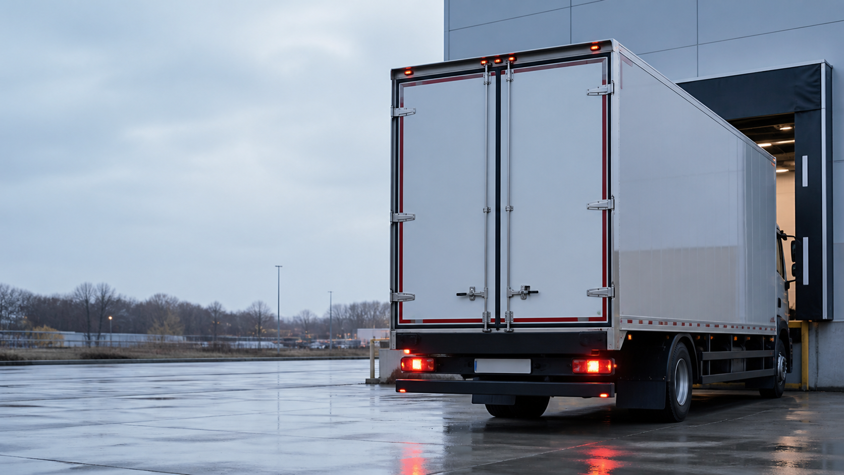
- rigid trucks approaching docks or working in congested yards;
- buses maneuvering near curbs and terminals;
- construction and mining equipment operating near people or obstacles;
- municipal and service vehicles with bodywork that blocks direct sightlines;
- agricultural or special-purpose machinery; and
- fleet retrofit projects that need a unified view rather than separate camera screens.
Before choosing hardware, map the actual blind areas and maneuvers. NIOSH provides methods and diagrams for understanding limited visibility around construction equipment. A simple site assessment can identify whether the priority is the ground immediately beside the vehicle, the rear travel path, a front corner, a loading interface, or a broader perimeter.
If only one defined rear blind area needs coverage, a well-positioned rear camera and monitor may be simpler and more economical. If the vehicle is articulated, carries interchangeable bodies, or changes geometry during operation, a standard stitched view may not represent every configuration. In those cases, use-case-specific cameras, sensors, or additional controls may be needed.
The eight decisions that define a reliable system
1. Define the vehicle and its operating configuration
Record overall length, width, and height; wheelbase; cab and body shape; mirror projection; attachments; articulation; and the normal position of moving equipment. Provide photographs from all four sides and from each proposed camera position.
Do not use only the base chassis drawing if the final body, crane, bucket, racks, or rear equipment changes the view. Identify whether a trailer is always present and whether the system is intended to visualize the tractor, the trailer, or both. A single calibration is tied to a specific geometry and camera position.
2. Define the visibility task
State what the operator must see and during which maneuver. Examples include low objects beside the wheels, a person near the rear corner, dock alignment, curb clearance, or general near-field awareness. Note the expected operating speed and whether the view is continuous or trigger-activated.
A bird’s-eye image optimized for ground-level clearance may not give the best detail for a distant rear view. Many systems pair the composite with a larger single-camera image for this reason.
3. Choose camera locations before choosing cable lengths
Camera positions need overlapping views and should be as stable, symmetrical, and unobstructed as the vehicle allows. Front and rear cameras are commonly centered; side cameras are commonly mounted on each side at comparable positions. The exact height and angle must follow the selected system’s installation guide.
Avoid locations where doors, mirrors, lifts, booms, tarps, or loads can block the lens. Consider stone impact, washdown, branches, and routine maintenance access. A bracket that flexes or is easily bumped can invalidate calibration even if the camera still produces an image.
4. Match cameras to the processor
The camera sensor, video mode, lens, image orientation, and processor profile work as a set. Substituting a “similar” fisheye camera may change distortion enough to prevent clean calibration. Confirm whether all four cameras must be the same model and whether front/rear housings differ from side-camera housings.
Check low-light requirements, ingress rating, operating-temperature range, vibration environment, and connector sealing for each exact model. These values are model-dependent. If infrared illumination is offered, evaluate possible reflection from vehicle surfaces.
5. Define the display and view behavior
Specify monitor size, brightness, mounting position, input format, and the screen layouts available. A four-channel monitor is not automatically a 360 processor; it may show four separate rectangles without generating a stitched bird’s-eye view.
Define what appears during normal travel, reverse, left turn, and right turn. Record trigger voltage and priority if more than one trigger is active. The display must be visible without obstructing the operator’s direct field of view or controls.
6. Design the power and cable architecture
Confirm nominal vehicle voltage, system input range, grounding method, fuse protection, ignition behavior, and power-off delay. Review electrical transients and installation requirements with a qualified vehicle electrician.
Measure cable routes through the actual chassis and body. Include articulation points, service loops, cab tilt, removable bodies, and connector access. Protect cables from heat, sharp edges, pinch points, chemical exposure, and abrasion. Long vehicles may require extension strategies specifically approved for the system.
7. Confirm the calibration method and space
Systems may use measured mats, checkerboard targets, tape-defined rectangles, parameter entry, automatic recognition, or manual point adjustment. The installer needs a sufficiently large, flat, well-lit area around the complete vehicle. Reflective, wrinkled, dirty, or poorly positioned targets can reduce recognition reliability.
Obtain the correct guide for the exact processor and software version. Do not copy target dimensions or camera angles from an unrelated system. Manufacturer instructions differ, and some values that work for a passenger car are unsuitable for a truck.
8. Define acceptance criteria
“Calibration successful” on the setup screen is only one checkpoint. Define what the operator and project team will accept: continuous coverage around the ground plane, reasonable alignment of straight reference lines, no missing critical zone at stitch boundaries, stable video while the engine runs, correct trigger views, and repeatable startup behavior.
Photograph the final mounting positions and save configuration files or parameter records where the system permits. A documented baseline makes later service and recalibration easier.
360° camera placement: what installers should prepare
The exact locations depend on the system, but five principles are consistent:
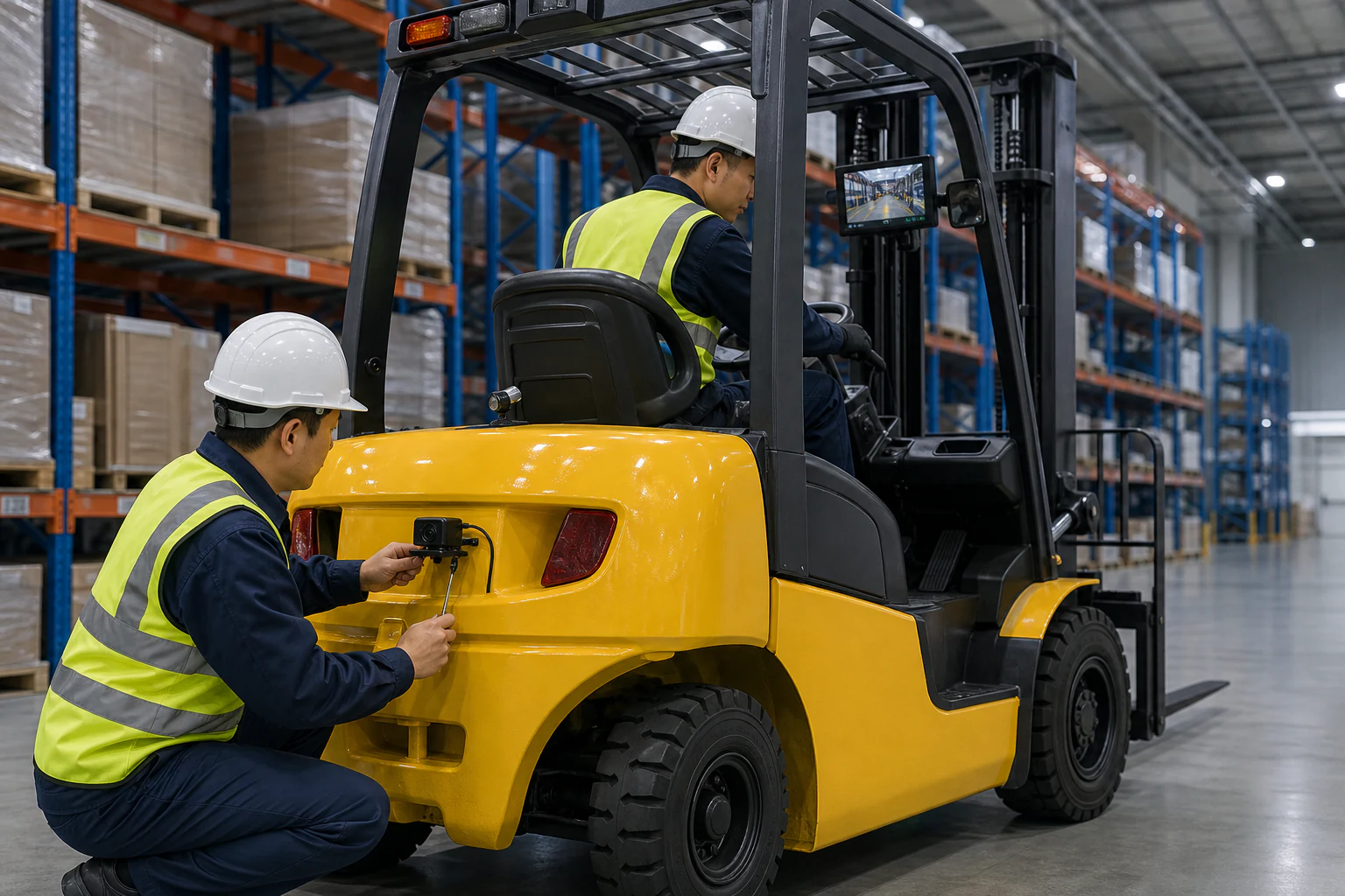
- Mount each camera to a structure that does not flex, rotate, open, or move relative to the calibrated body.
- Keep left and right positions as consistent as the vehicle permits; document unavoidable differences.
- Preserve the overlapping views required for targets and adjacent cameras, with the vehicle in its normal operating configuration.
- Protect the lens from impact and contamination without allowing a hood, mirror, step, boom, or load to obstruct the fisheye image.
- Use brackets that adjust predictably and lock firmly. Mark approved positions, seal body penetrations correctly, and obtain authorization before drilling or modifying equipment.
Calibration preparation and workflow
Always follow the exact product manual, but a robust project workflow usually includes the following stages.
Stage 1: mechanical inspection
Park the vehicle on a flat surface in its normal configuration. Set the parking brake, isolate movement as required, and create a controlled work area. Confirm tire condition, suspension state, and body position if these affect height. Clean each lens and ensure every bracket is tight.
Measure and record camera positions. Check that the vehicle body is visible in each raw image as required by the manual and that calibration targets will fit fully within the field of view.
Stage 2: target placement
Lay out the specified mats or patterns using accurate measurements from defined vehicle reference points. Keep the material flat and matte enough for the camera to distinguish the pattern. Use lighting that avoids deep shadows and strong reflections.
Do not move the vehicle, cameras, or targets once measurement begins. Large equipment may need a dedicated bay or cleared yard. Plan this space before the installation date; calibration cannot be completed reliably in a narrow service lane simply because the wiring is finished.
Stage 3: parameter entry and image recognition
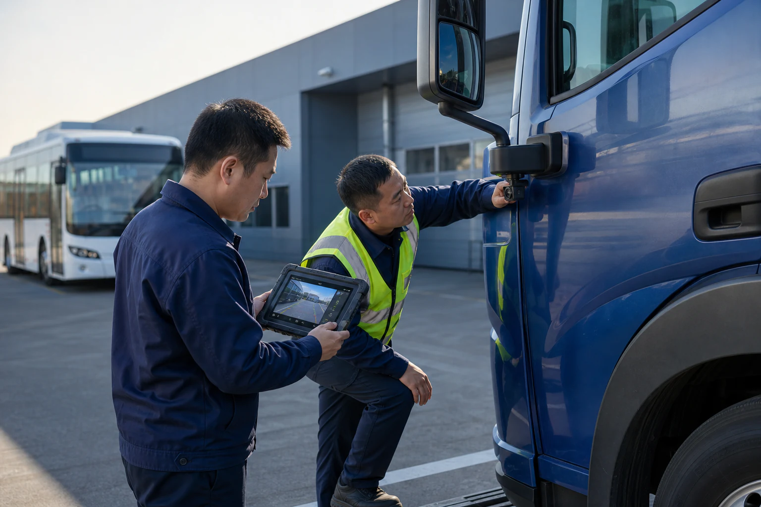
Enter vehicle dimensions and camera-related parameters exactly as defined by the system. Select the correct lens or vehicle profile. Check the raw view from all four cameras before starting automatic calibration.
If target recognition fails, investigate target visibility, lighting, focus, exposure, camera angle, measurement, and obstruction. Repeatedly pressing “calibrate” without correcting the setup rarely solves the underlying problem.
Stage 4: stitch review and manual refinement
Inspect straight lines that cross camera boundaries and objects placed near critical zones. Minor visual discontinuity can occur because the image is synthesized, but a missing ground area, severe overlap, or misleading position needs correction.
If the system permits manual control points, adjust them methodically and save a backup of the approved configuration. Manual correction should refine a sound installation, not compensate for a loose camera or incorrect target layout.
Stage 5: operational validation
Remove all targets and test in a controlled area at startup, with the engine running, and with relevant electrical equipment active. Check every trigger and move slowly past safe reference objects. Evaluate daylight, low light, glare, vibration, latency, and wet conditions where relevant. The view should support the task without encouraging the operator to ignore direct observation.
Why 360° calibration fails
A camera moved after calibration
Even a small bracket shift changes the mapping. Inspect fasteners and reference marks, then recalibrate if the position has changed.
The target is incomplete or reflective
Wrinkles, glare, shadows, incorrect dimensions, or a pattern outside the camera view can cause detection errors. Use the specified target and controlled lighting.
Vehicle measurements are wrong
Entering body width where the system expects a different reference dimension distorts the composite. Follow the manual’s measurement points rather than assuming the field names are self-explanatory.
Camera models or lens profiles do not match
Image correction depends on the expected lens. Confirm part numbers and the selected configuration profile.
Camera heights or angles are outside the supported range
A convenient mounting location may not provide the overlap required by the processor. Review the raw images and installation limits before final drilling.
Bodywork blocks a critical part of the image
Steps, mirrors, bumpers, lifting mechanisms, or open panels may obscure the target or operating zone. Reconsider placement rather than attempting to calibrate through the obstruction.
Poor power or signal integrity
Intermittent video, noise, or a camera that resets will undermine calibration. Test voltage at the device and inspect the complete cable path and grounds.
Factory testing and shipment inspection
Factory testing can confirm that the supplied cameras, processor, monitor, cables, triggers, and accessories function as the approved kit. The test should use the ordered video format and representative cable arrangement. Confirm raw images on all channels, view switching, processor output, menu access, storage or recording functions if included, and the selected language or vehicle profile.
Shipment inspection should compare the packed bill of materials with the approved list. Verify camera positions or labels (front, rear, left, right), cable lengths, connector types, calibration materials, remote control or setup interface, brackets, fasteners, manuals, and spare parts. Inspect packaging so lenses, displays, and connectors cannot strike each other during transport.
Factory testing cannot validate the final stitched image without the target vehicle or a representative fixture. Keep this distinction clear in the purchase agreement: the supplier validates product function and configured components; the installer validates mounting, calibration, and performance on the vehicle.
Pilot installation before fleet rollout
Start with one representative vehicle for each materially different body or equipment type; a rigid truck and a tractor-trailer should not automatically share one approved installation. The pilot should produce:
- an approved bill of materials and cable-length schedule;
- marked camera positions with measurements and photos;
- bracket and body-sealing method;
- wiring diagram, fuse, ground, and trigger connections;
- calibration target layout and saved parameters;
- acceptance-test results for critical zones;
- operator and maintenance instructions; and
- a record of conditions that require inspection or recalibration.
After several weeks, inspect bracket movement, contamination, cable wear, connector sealing and operator feedback. This reveals the maintenance burden before a larger shipment.
Buyer’s request-for-quotation checklist
Send the following information with the inquiry:
- Vehicle or machine type, make/model, body/attachment description, and quantity.
- Overall dimensions and four-side photographs or drawings.
- Required blind-area coverage and typical maneuver.
- Proposed camera mounting locations and height constraints.
- Display location, size preference, input/output needs, and view layout.
- Vehicle voltage, ignition behavior, and trigger requirements.
- Measured cable routes, articulation, removable-body, or cab-tilt requirements.
- Operating temperature, water, dust, washdown, vibration, and lighting conditions.
- Need for recording, overlays, parking lines, or integration with an existing display/DVR.
- Installer capability, calibration space, sample schedule, target quantity, and OEM branding needs.
Frequently asked questions
How many cameras does a truck 360 system use?
Most stitched around-view systems use four wide-angle cameras: front, rear, left, and right. Additional cameras may support other tasks, but they are not automatically part of the stitched view. Confirm the processor’s supported channels and layouts.
Can a 360 camera system be installed on any truck?
Not automatically. The vehicle must provide suitable stable mounting locations, overlapping views, cable routes, power, display integration, and enough space for the specified calibration method. Long, articulated, or shape-changing vehicles require special review.
Does a four-channel monitor create a bird’s-eye view?
No. A standard four-channel monitor may display four separate camera images. A stitched bird’s-eye view requires a compatible around-view processor and calibrated cameras.
Why do objects look stretched in the 360 view?
The processor transforms fisheye images onto a ground-plane model. Tall objects and items near stitch boundaries can appear distorted, split, or stretched. Evaluate ground-level spatial awareness and use a dedicated single-camera view when more detail is needed.
When should the system be recalibrated?
Check calibration after a camera or bracket moves, bodywork is repaired, ride height changes materially, a camera is replaced with a different model, or the composite no longer aligns with known references. Follow the manufacturer’s service guidance.
Is a 360 camera a substitute for a spotter or mirrors?
No. It is a visibility aid. Operators must follow applicable training, direct-observation, mirror, spotter, traffic-management, and workplace requirements. The final safety procedure belongs to the fleet or site operator.
Conclusion
A reliable 360° system begins with the vehicle and the visibility task, not the product carton. Document geometry, blind areas, camera positions, display behavior, power, cables, environment, and calibration resources before selecting the kit. Then treat the first installation as an engineering pilot with measurable acceptance criteria.
Matched components and factory inspection reduce product-level risk, but correct mounting and calibration determine the final image. When those responsibilities are documented from quotation through shipment and installation, a fleet can reproduce the approved configuration and maintain it over time.