

Start with the truck configuration
Record whether the project uses rigid trucks or tractor-trailer combinations. Include cab layout, body length, trailer types, coupling arrangements and whether tractors exchange trailers. These affect viewing positions and cable routes; selecting a camera count alone does not resolve them.
Photograph the representative truck and mark the proposed camera and cab-display positions. Use the Truck application views as a starting point, then note where the customer’s body or trailer differs.
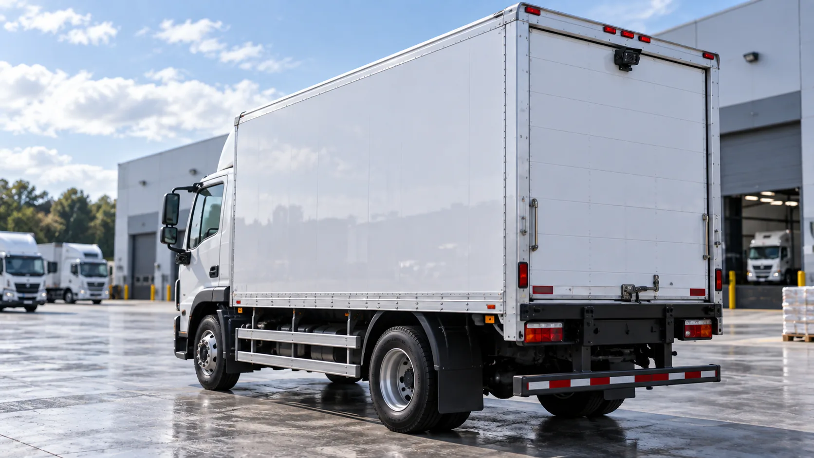
Compare proposals by truck and trailer arrangement
| Vehicle arrangement | Detail to put in the quotation | Sample check |
|---|---|---|
| Rigid body | Rear mounting location and protected cable route | Check the image with fitted body equipment in its intended operating position |
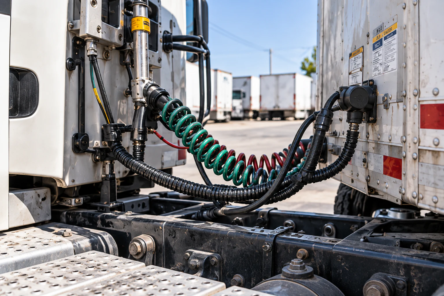
| Articulated tractor and trailer | Moving connection, cable protection and service access | Review the route through the intended articulation range |
| Tractors exchanging trailers | Approved connector pinout and identification for every combination | Couple each proposed tractor and trailer type and verify the view |
| Different body lengths | Route measurement for each variant | Confirm that extensions and mounting hardware match the supplied body |
| Several driver views | Monitor input capacity and documented selection priority | Operate the required inputs together and verify the displayed view |
Keep each requested view tied to a task. The side view comparison covers lateral visibility; the backup camera comparison covers the rear manoeuvring view. A multi-input monitor specification does not establish multi-channel recording.
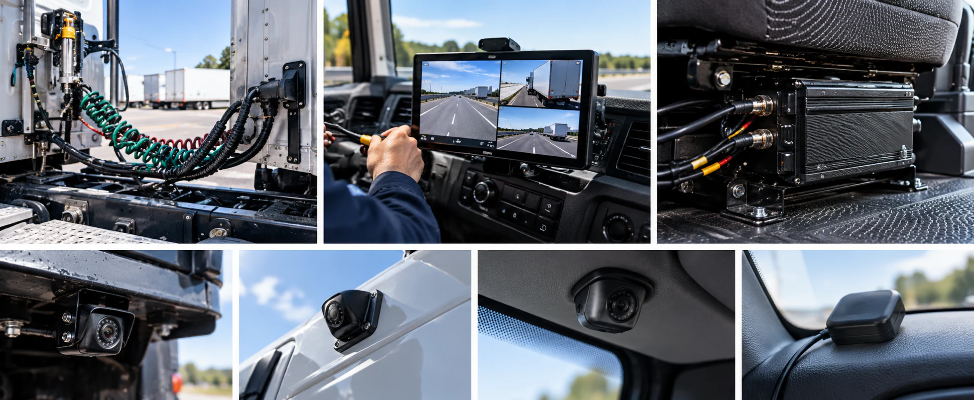
Inspect mounting and articulation before quoting cable
Mounting position and useful image
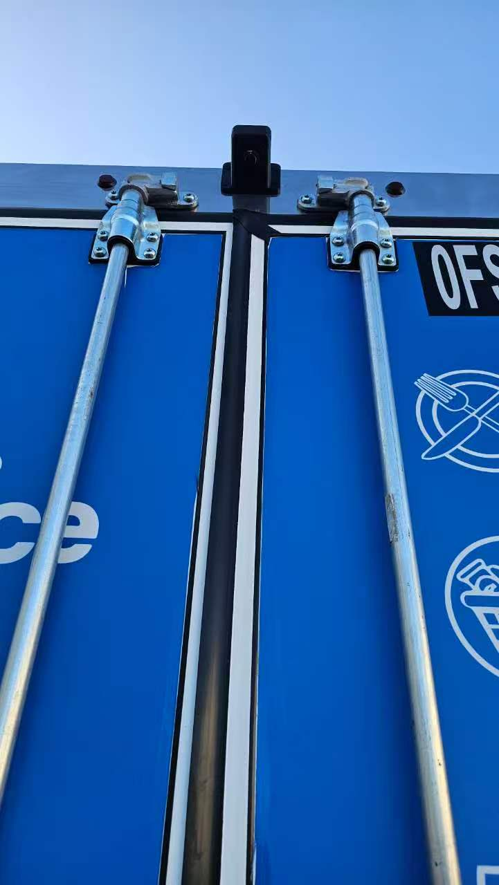
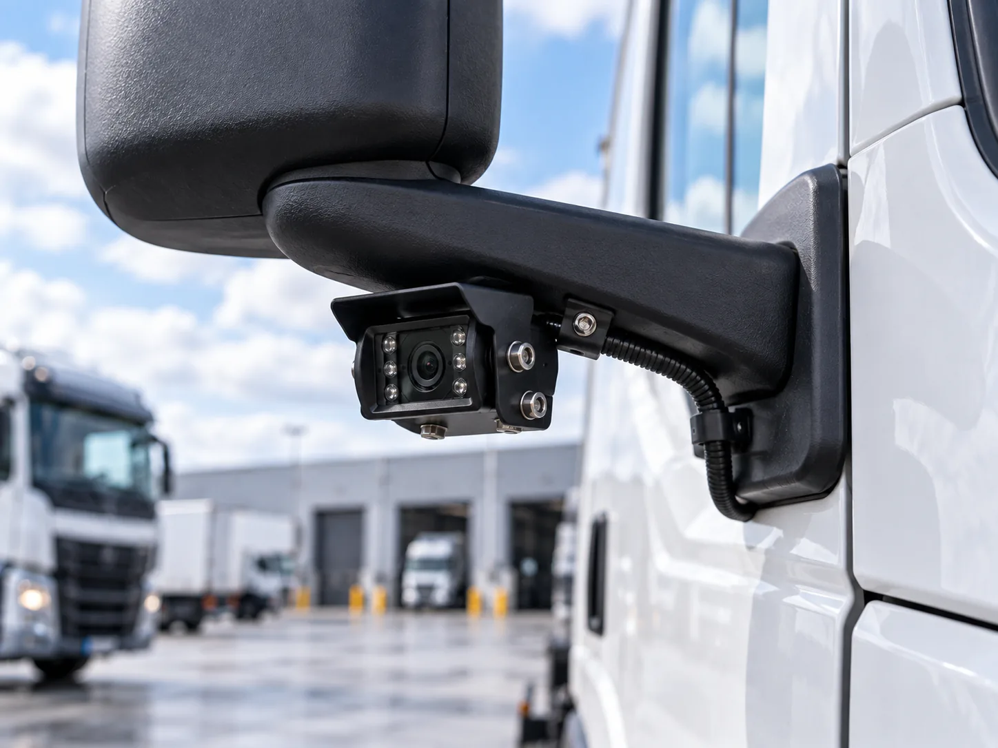
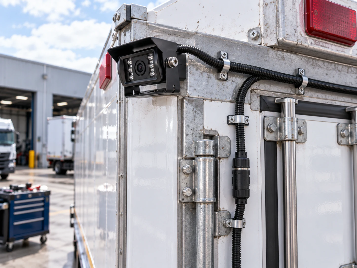
Ask for a proposed location and sample image from that location. Consider bodywork, loads and equipment that may obstruct the lens. Review the image from the normal driver position and define the area that must remain visible. Lens angle and housing dimensions are model-dependent; a catalog photo does not establish a useful installed view.
Cable route and trailer changes
Have the installer measure the protected route rather than estimating from overall vehicle length. Record moving joints, coupling points and exposed sections. For interchangeable trailers, agree connector identification and approved combinations. Verify the connection after coupling changes during the sample process; physically matching sockets may not share a pinout.
Confirm the receiving display and power path
List camera output, monitor input, component voltage, connectors and extensions in one bill of materials. Keep vehicle supply voltage separate from the voltage delivered to each component; confirm any regulation in the proposed arrangement. Use the AHD versus CVBS guide for receiver compatibility. Agree manual or vehicle-triggered view selection and check priority if multiple triggers are supported.
Shortlist individual cameras in the vehicle camera category, then ask for a complete assembly quotation. Include brackets, measured cable lengths, installation responsibility and replacement configuration so competing proposals cover the same truck variants.
Use a truck-specific sample acceptance checklist
- Required rear and side areas are identified on the actual body configuration.
- Mounts and cable routes are checked, including moving connections.
- Signal, power, pinout and display selection are documented.
- The driver can use each required view from the normal seating position.
- Day and intended low-light conditions are included in sample review.
- Recording has a separate retrieval acceptance step if required.
- Replacement components and trailer connection standards are recorded.
Cameras support the driver’s view and do not replace mirrors, observation or operating procedures. Record the sample findings for each approved truck and trailer combination.
For related application planning, see Truck Camera Applications.
Prepare the truck project inquiry
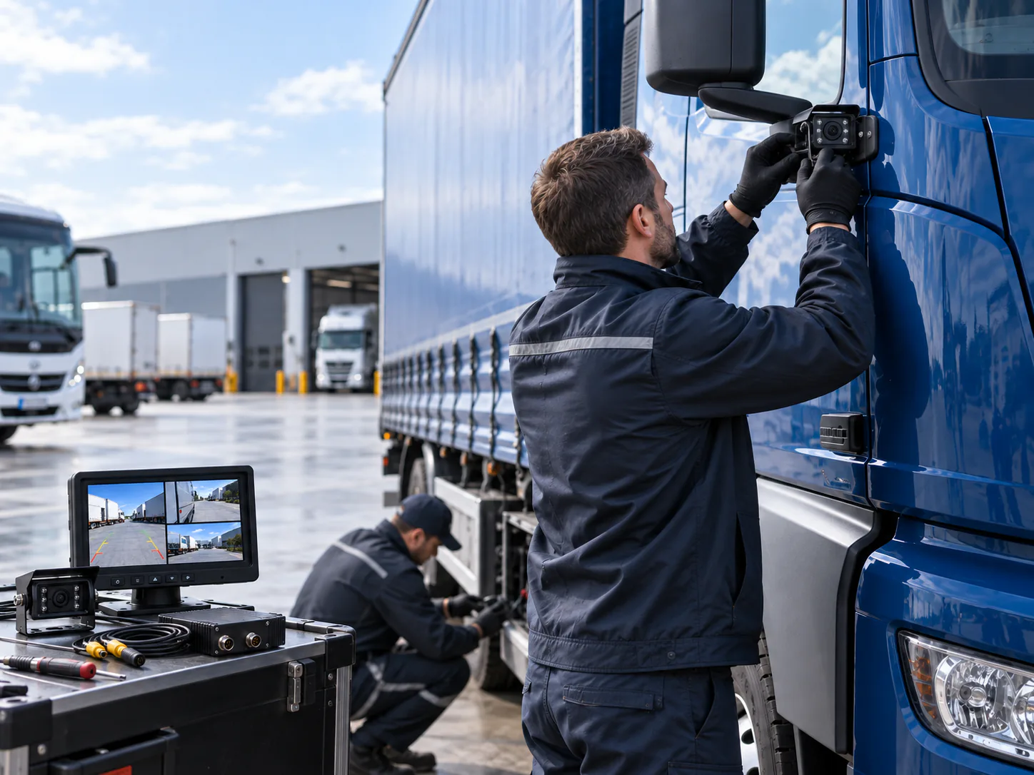
Send truck and trailer types, mounting photos, required views, display location, measured cable route and sample quantity. For recording across multiple vehicles, continue to the fleet dash cam guide, which focuses on retrieval, maintenance and rollout approval.

